06 4012 5121
EN NL

Useful information

Structure and load paths - chimney drawings

Understand how the parts interact. Load paths, bearings, floor connections and temporary conditions require a design based on the actual property.

These are principle drawings, not drawings of your property. Dimensions, support arrangements and execution details require a site assessment and, where needed, a structural design.

SV-05 · Principle detail

Load path and structural interaction

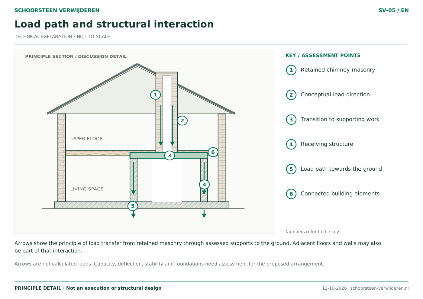
Arrows show the principle of load transfer from retained masonry through assessed supports to the ground. Adjacent floors and walls may also be part of that interaction.
Load path and structural interaction
Open the drawing to zoom into the vector detail.

How to read this drawing

  1. Retained chimney masonry
  2. Conceptual load direction
  3. Transition to supporting work
  4. Receiving structure
  5. Load path towards the ground
  6. Connected building elements

What needs assessment?

Arrows are not calculated loads. Capacity, deflection, stability and foundations need assessment for the proposed arrangement.
SV-06 · Principle detail

Bearing and support arrangement

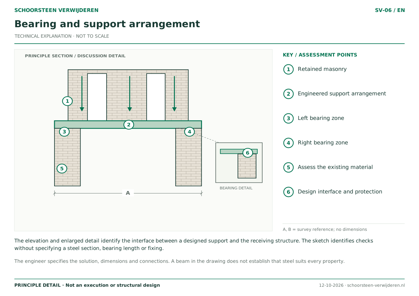
The elevation and enlarged detail identify the interface between a designed support and the receiving structure. The sketch identifies checks without specifying a steel section, bearing length or fixing.

Bearing and support arrangement
Open the drawing to zoom into the vector detail.

How to read this drawing

  1. Retained masonry
  2. Engineered support arrangement
  3. Left bearing zone
  4. Right bearing zone
  5. Assess the existing material
  6. Design interface and protection

What needs assessment?

The engineer specifies the solution, dimensions and connections. A beam in the drawing does not establish that steel suits every property.

SV-07 · Principle detail

Floor opening in plan

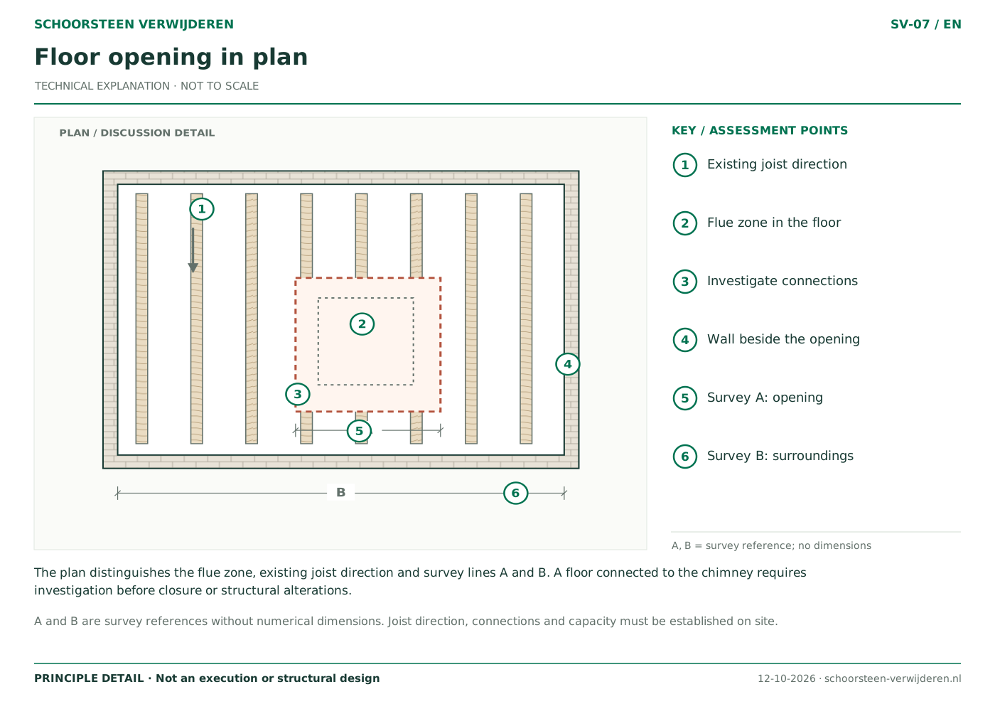
The plan distinguishes the flue zone, existing joist direction and survey lines A and B. A floor connected to the chimney requires investigation before closure or structural alterations.

Floor opening in plan
Open the drawing to zoom into the vector detail.

How to read this drawing

  1. Existing joist direction
  2. Flue zone in the floor
  3. Investigate connections
  4. Wall beside the opening
  5. Survey A: opening
  6. Survey B: surroundings

What needs assessment?

A and B are survey references without numerical dimensions. Joist direction, connections and capacity must be established on site.

SV-08 · Principle detail

Temporary conditions in the work plan

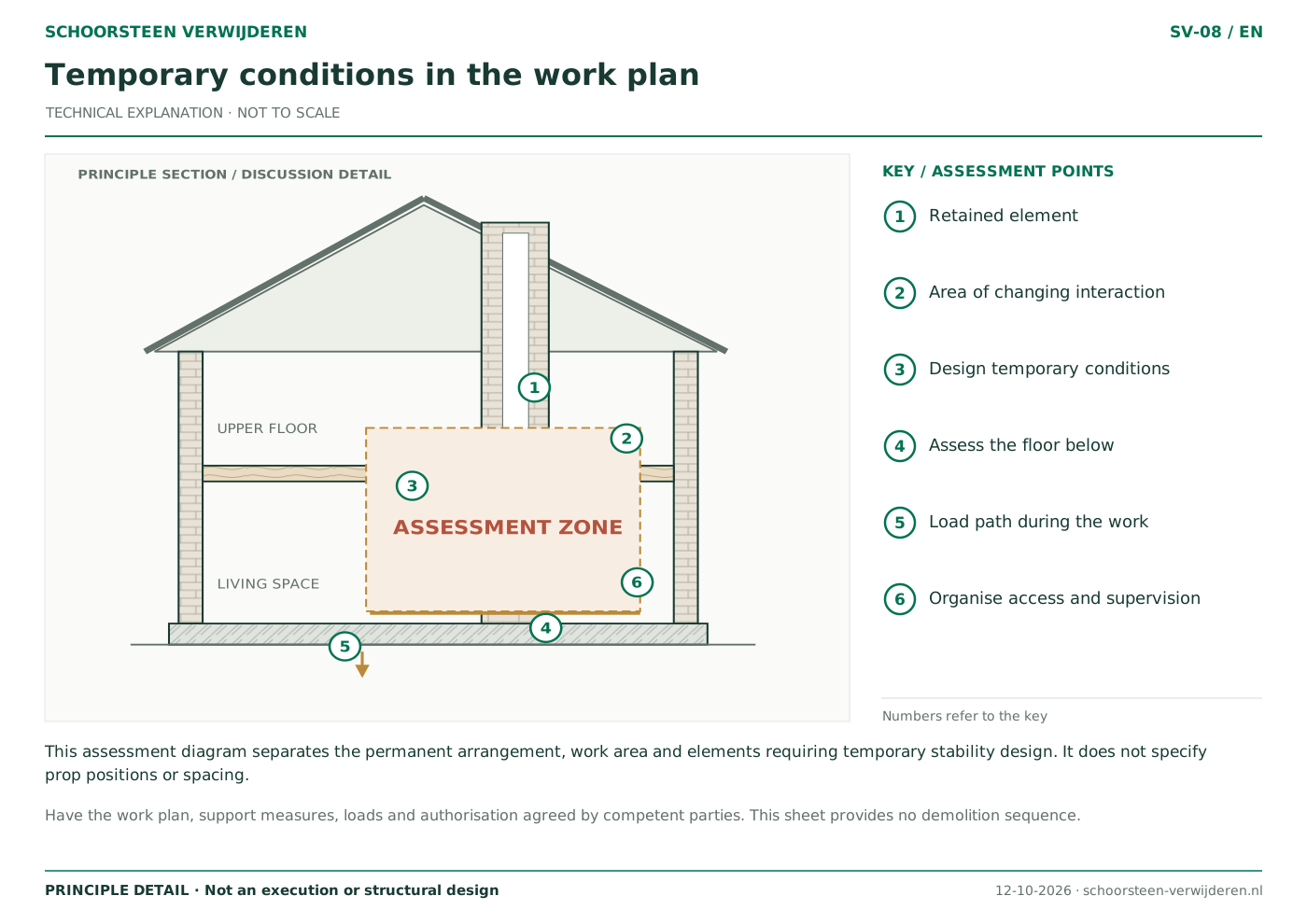
This assessment diagram separates the permanent arrangement, work area and elements requiring temporary stability design. It does not specify prop positions or spacing.

Temporary conditions in the work plan
Open the drawing to zoom into the vector detail.

How to read this drawing

  1. Retained element
  2. Area of changing interaction
  3. Design temporary conditions
  4. Assess the floor below
  5. Load path during the work
  6. Organise access and supervision

What needs assessment?

Have the work plan, support measures, loads and authorisation agreed by competent parties. This sheet provides no demolition sequence.

Read the detailed guides

From a principle to a drawing for your home

Include the address, existing plans, photographs, the parts to remain and your preferred finish with your enquiry. A designer or structural engineer establishes which measurements, investigations and documents are needed.

Background and sources

Editorial review: . No engineering approval for a specific property.

IPLO: drawings and calculations for permit applications ↗Omgevingsloket: check the work at your address ↗